Satellite communication is a wireless communication method that uses satellites as a communication medium. When chatting with customers and friends, I often encounter customers and friends who are not very familiar with some terms in satellite communication. Later, we will introduce the relevant knowledge of satellite communication in very popular words in several times. We strive to make it 100% understandable even if you do not have a professional technical background in the communications and electronics industry.
This time, we try to introduce satellite communication phased array antenna in the most popular way.
Before introducing the phased array antenna, let us first briefly talk about the most commonly used parabolic antenna in satellite communications.
Parabolic antenna
The basic principle of parabolic antenna
Here is a picture of a parabolic antenna:
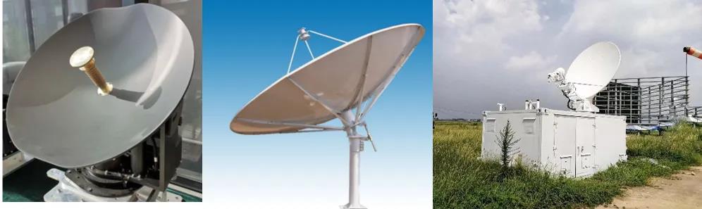
Everyone should be familiar with it. In the fields of TV live broadcast, emergency rescue, etc., we can often see this parabolic antenna used for satellite communication. From the appearance, the parabolic antenna looks like an upturned pot, so it is also commonly known as the "pot antenna" in the industry.
The dish of a parabolic antenna is a curved surface. We learned about the focus of a curved surface in middle school. A quadratic surface has a definite focus. All satellite signals parallel to the axis that shine on the curved surface will be focused to the focus of the curved surface, as shown in the figure below.
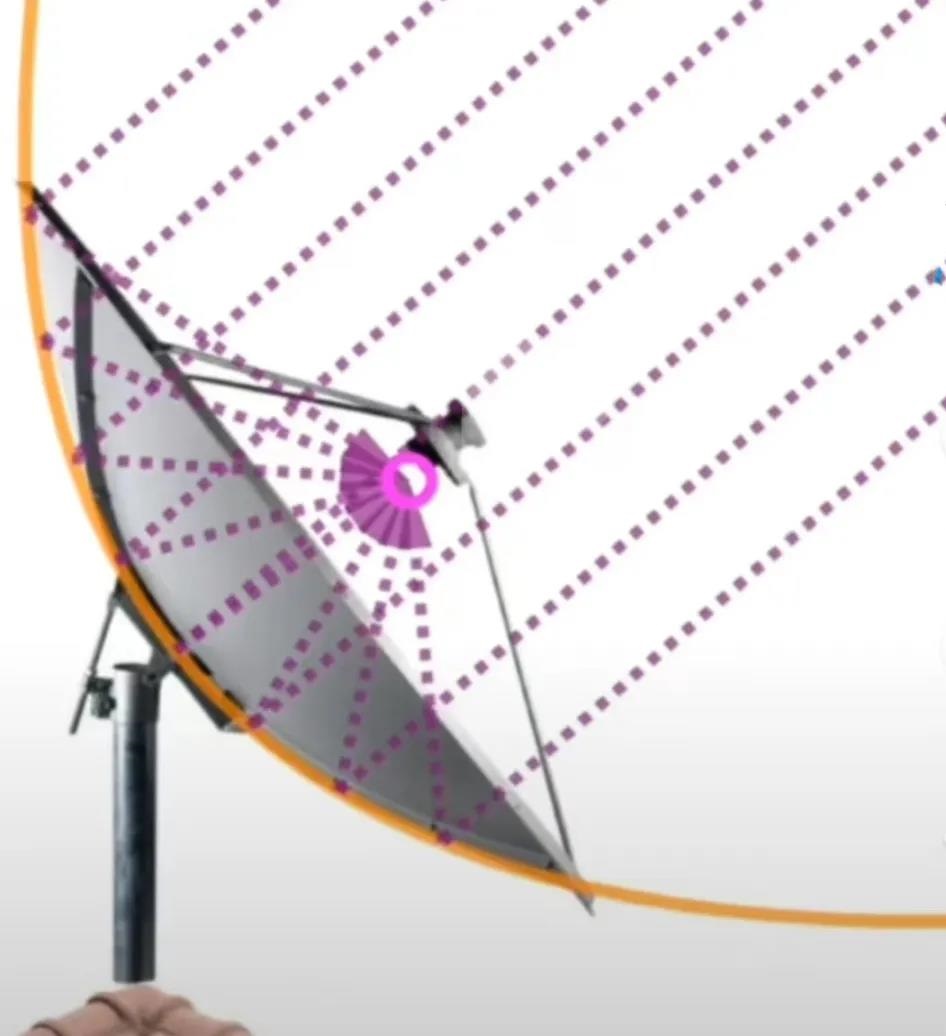
Well, if we place an antenna feed (which can be considered as a signal receiver) at the focus of the surface, the power of the satellite signal received by this feed can be considered as the sum of the powers of all satellite signals that are irradiated parallel to the surface.
In this way, the power of the received satellite signal is amplified. There is a special term here, the antenna gain Gain, which can be understood as the antenna's amplification of the signal. From the above analysis, we can know that the gain of the parabolic antenna is related to the area of the surface. The larger the area of the surface, the more satellite signals are incident on the surface, the stronger the signal power gathered at the focus of the surface, and the greater the antenna's amplification (gain) of the satellite signal.
Tip: The antenna's gain is proportional to the square of the antenna's aperture area.
Parabolic antenna to satellite
In order to achieve the purpose of amplifying satellite signal power, the axis of the parabolic antenna must be aimed at the satellite. Because if the parabolic antenna is not aimed at the satellite, even if there is a satellite signal shining on the dish, the signal path is not parallel to the axis, and it cannot be guaranteed that all incident signals will be focused on the focus.
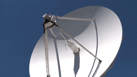
So how do we ensure that the parabolic antenna is pointed at the satellite? The antenna is mounted on a servo turntable, which can rotate in three degrees of freedom: azimuth, pitch, and polarization. By rotating the turntable, the parabolic antenna can be pointed at the satellite.
Therefore, the parabolic antenna has two characteristics:
The antenna must be aimed at the satellite through the mechanical rotation of the turntable, and the response speed of the antenna to the satellite depends on the mechanical servo structure of the turntable.
The height of the antenna is relatively high. For example, if the diameter of the antenna is 0.6m, the antenna diameter plus the height of the turntable must be more than 0.6m. For example, the following airborne antenna.
Phased Array Antenna
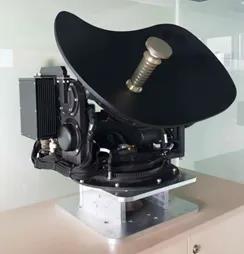
Let's look at another type of satellite communication antenna: the phased array antenna. Below is a product image of a phased array antenna:
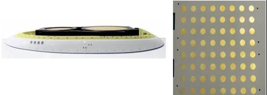
From the figure we can see that there are obvious differences between phased array antennas and parabolic antennas:
There is no mechanical transmission;
The height of the antenna is low.
Basic principles of phased array antennas
Without a mechanical transmission device to rotate the antenna, how does the phased array antenna aim at the satellite? Here we have to talk about the basic principles of the phased array antenna. Some of you may have heard of technical parameters such as T/R components, phase shifters, electronic scanning, beam scanning, off-axis angle, scanning time, etc. Below we will use the simplest words to explain the basic principles of the phased array antenna.
Generally, the phased array antenna of satellite communication is composed of dozens, hundreds or even thousands of antenna elements. Let's first look at the case of two antenna elements. As shown in the figure below.
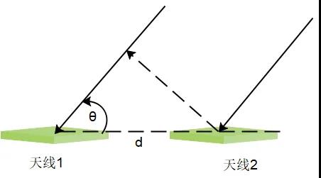
In this figure, there are two antennas installed side by side. The distance between the two antennas is fixed, which we represent with d, and is generally half a wavelength.
What is wavelength? Wavelength = signal frequency / electromagnetic wave propagation speed. If the frequency is 12GHz and the electromagnetic wave propagation speed is 3*10^8 m/s, then the wavelength of the signal is 0.025m.
The satellite signal is incident on two antennas. Due to the different positions of the two antennas, the phases of the signals received by the two antennas will also be different. For example, the signal received by antenna 1 is S1=Asin(ψ1), and the signal received by antenna 2 is S2=Asin(ψ2). What is the phase difference Δψ=ψ2-ψ1 between S1 and S2?
Since the distance between the two antennas is fixed, which is d, if the incident angle θ of the satellite signal is known, then we can calculate the distance difference between the signal received by antenna 2 and the signal received by antenna 1 = d*sin θ.
When we know the frequency f of the satellite signal, we know the wavelength λ of the signal, and then we can convert the distance difference into a phase difference Δψ=ψ2-ψ1= 2π * d* sin θ/ λ.
What will happen if we directly add the signal S1 received by antenna 1 and the signal S2 received by antenna 2?
According to the knowledge of trigonometric functions learned in middle school, we know that since there is a phase difference between the two sine waves, the amplitude of the sum after adding them must be less than 2A, as expressed in the following formula:
Asin(ψ1) +Asin(ψ2) =2A*sin((ψ1+ψ2)/2)*cos((ψ1-ψ1)/2).
At this point let us think about it, if we adopt a method to eliminate the phase difference between S1 and S2, and make the phase of S2 the same as the phase of S1, ψ1=ψ2, and at this time we still directly add S1 and S2, what will happen?
S1+S2=2*Asin(ψ1)。
Obviously, at this time, the amplitude of the direct addition of the signal S1 received by antenna 1 and the signal S2 received by antenna 2 is 2A, so we have amplified the signal amplitude by 2 times.
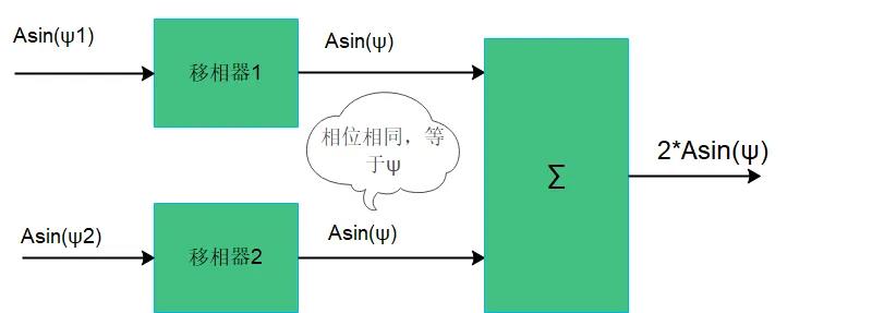
Well, how can we make the phase of S2 consistent with the phase of S1 in engineering? Here we use a phase shifter. As the name suggests, a phase shifter is a module that can move the phase of a signal. We don't need to care about how the phase shifter works, we just need to know:
A phase shifter can shift the phase of a signal, and the amount of phase shift can be controlled.
Let's look at the figure below. We have added phase shifters to the back end of antenna 1 and antenna 2. By controlling the signal phase values moved by the two phase shifters, we can make the phase of the S1 signal passing through phase shifter 1 equal to the phase of the S2 signal passing through phase shifter 2. Then after the phase shifter, we add the two signals together, and the amplitude of the addition result is 2A.
The above is the simplest case of two antennas. What if there are 4 antennas, 16 antennas, 256 antennas, or 512 antennas? In fact, they are all the same. The antennas are arranged according to certain rules, and the distance d between the antennas is fixed and known. A phase shifter is connected behind each antenna, for example, there are 4 phase shifters, 16 phase shifters, 256 phase shifters, and 512 phase shifters. Then, taking a certain antenna as the reference (assuming it is antenna No. 1), adjust the phase value of the phase shifter corresponding to the other antennas so that the signal phases output by all phase shifters are the same. Finally, add all the signals together. The signal amplitude after addition is 4A, 16A, 256A, and 512A, and the signal is amplified by 4 times, 16 times, 256 times, and 512 times.
That is to say, the satellite signal at this incident angle is amplified N times.
Due to differences in production process, installation position, device performance, etc., there are deviations in the amplitude and phase of each antenna unit and RF component, and it is necessary to compensate the amplitude and phase of each signal receiving branch. Therefore, the signal after each phase shifter is multiplied by an amplification factor to compensate for the signal amplitude.
Therefore, we can get the simplest structure of the phased array antenna as follows:
Now with the development of integrated circuit technology, all of the above devices have been made into chips and no longer need to be built with RF analog devices as in the past.
The low noise amplifier in front of the picture is present in all antenna systems and has nothing to do with the principle of phased array.
The above is the basic principle of the phased array antenna. By adjusting the phase of the phase shifter, the phase of the incident signal is changed, and the amplitude of the incident signal is changed, and finally the maximum gain is formed in the direction of the incident angle.
If the satellite is located exactly in the direction of the incident angle of the phased array antenna, the satellite signal is amplified with the maximum gain.
Phased Array Antenna Control
From the above introduction, we know that the phased array antenna adjusts the phase of the phase shifter, and this adjustment process is related to the incident angle of the satellite signal. If the incident angle of the satellite signal is determined, and the frequency of the satellite signal is determined, then we can calculate the phase of the phase shifter of the phased array antenna, thereby controlling the phased array antenna to have the best signal gain in the direction of the current signal incident angle.
In other words, as long as we tell the phased array antenna the incident angle and frequency of the satellite signal, the phased array antenna will achieve the maximum gain in the direction of the incident angle. In industry terms, it can be expressed as follows: the beam generated by the phased array antenna is aimed at the satellite, and the satellite signal obtains the maximum gain.
What if the incident angle of the satellite signal changes due to the change in the attitude of the platform on which the antenna is located? We can calculate the incident angle of the satellite signal under the new attitude condition, and then tell the new incident angle to the phased array antenna. The phased array antenna will form the maximum gain in the direction of the new incident angle, that is, a new beam is generated, which is still aimed at the satellite.
The basic control process of the phased array antenna can be simply represented by the following figure:
The incident angle of the satellite signal can be calculated through the position of the satellite, the position of the antenna, and the attitude of the antenna platform (azimuth, pitch, roll).
The incident angle of the satellite signal, the frequency of the signal and other information are told to the antenna controller, and the antenna controller controls the internal circuit of the antenna to change the phase of the phase shifter.
The following video is a video of the company's phased array antenna prototype development stage, where the antenna is tracked and controlled on a 6-DOF swing platform. We can see that the antenna itself does not have any mechanical servo structure, and there is no relative motion between the antenna and the platform. The antenna beam is kept pointed at the satellite through electronic scanning.
Advantages and Disadvantages of Phased Array Antennas
Advantage
Low height, low profile, low installation height requirement, especially suitable for scenes with limited installation space such as airborne;
Adopt electronic scanning, fast response speed.
Generally speaking, the switching time for a phased array antenna beam pointing angle to switch from one angle to another is less than 1ms, which is far beyond the reach of a mechanically scanned parabolic antenna, because when a parabolic antenna switches its direct pointing angle, it needs to rely on a motor to drive the gears to rotate.
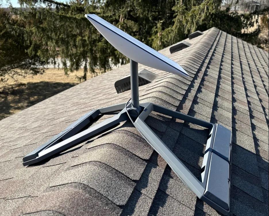
Phased array antennas are particularly suitable for highly maneuverable carriers, such as aircraft with high-speed maneuvers. In addition, in low-orbit satellite communication systems, since low-orbit satellites move very fast and parabolic antennas have a long response time, it is difficult to track low-orbit satellites. Currently, low-orbit satellites all use phased array antennas. For example, the ground receiving antenna of the Starlink system is a phased array antenna, as shown in the following figure:
shortcoming
cost
If the same antenna gain is to be achieved, the cost of a phased array antenna will be much more expensive than a parabolic antenna.
Effects of low elevation angles
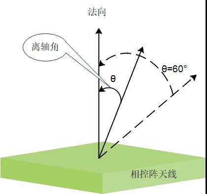
Phased array antennas have a characteristic: the gain in the antenna normal direction (that is, the direction perpendicular to the antenna surface) is the highest, and as the incident angle increases from the normal direction, the gain decreases. If the satellite is directly above the antenna, the satellite incident signal is consistent with the antenna normal, and the gain of the phased array antenna is the highest. If the satellite is not directly above the antenna, and the satellite incident signal deviates from the antenna normal at an angle, the gain of the phased array antenna decreases, and the greater the angle deviation, the lower the gain of the antenna. The angular deviation between the satellite incident signal and the antenna normal is called the "off-axis angle" in the industry.
When the off-axis angle is equal to 60 degrees, the antenna gain of the signal incident from this angle will be reduced by 4dB relative to the normal gain. This is a characteristic of the phased array antenna itself and cannot be overcome.
Let's take a high-orbit satellite as an example. If the phased array antenna is near the equator, the off-axis angle between the satellite and the antenna normal is small, and the antenna gain is high. As the latitude increases, the off-axis angle between the satellite and the antenna normal becomes larger and larger, and the antenna gain becomes smaller and smaller. Therefore, the use of phased array antennas is subject to certain restrictions in high-latitude areas.
Therefore, when using phased array antennas, we need to calculate the off-axis angle of the phased array antenna based on the area used by the user, and then estimate the reduction in antenna gain based on the off-axis angle, leaving enough margin when making the satellite communication link budget.